Quadcopter Flight
J.Gong
2026-03-28
4.56min
Quadcopter Flight
1. Introduction to Quadrotor Systems
A quadcopter, also frequently referred to as a quadrotor, is a type of multirotor helicopter or rotary-wing Unmanned Aerial Vehicle (UAV) that utilizes four rotors to achieve flight (Luukkonen, 2011). These rotors are typically directed upwards and arranged in a square formation, with each rotor positioned at an equal distance from the center of mass. In this configuration, the four actuators are generally equally spaced by 90° from one another (Idrissi et al., 2022).
1.1 Historical Context
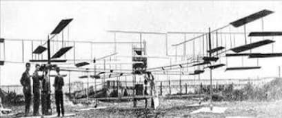
The origins of quadrotor technology date back to 1907, when the Breguet brothers constructed the Gyroplane No. 1 (Figure 1). While this marked one of the first manned helicopter flights, it was not a free flight; the machine lacked inherent stability and a proper control mechanism, requiring it to be tethered to the ground (Ghazbi et al., 2016).
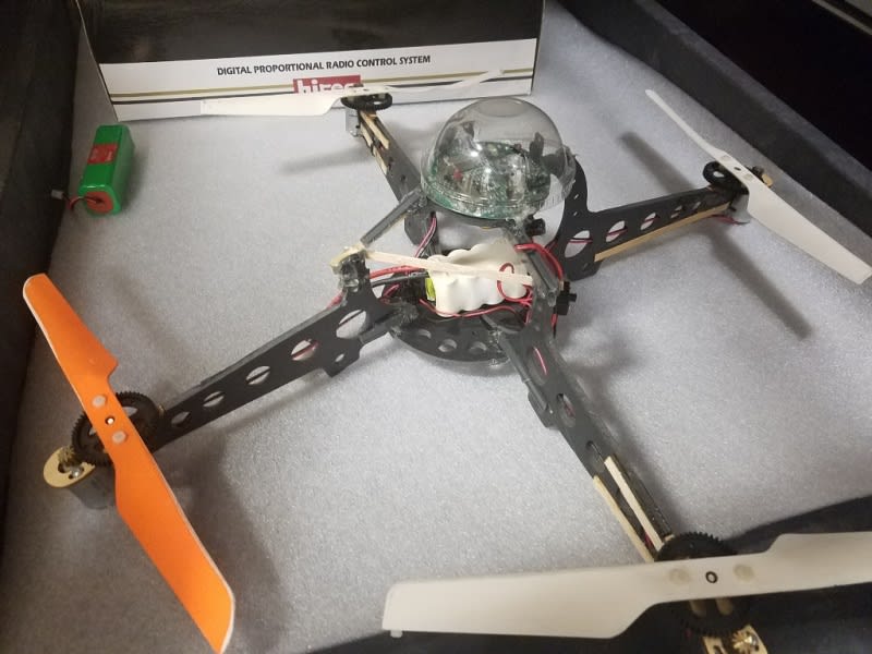
The transition to modern UAVs occurred in the late 1990s. A pivotal moment was the 1999 release of the Draganflyer I (Figure 2), the first camera-equipped quadrotor to achieve mass production. This shifted quadrotor technology from a laboratory curiosity to a viable commercial product (Karahan, 2025).
1.2 Modern Applications
Since 2010, advancements in micro-electronics and control theory have expanded the use of quadrotors across various sectors:
- Public Safety: Search and rescue, firefighting, and border surveillance.
- Agriculture: Precision seeding, chemical spraying, and crop monitoring.
- Commercial: Last-mile delivery and high-end cinematography.
2. Flight Dynamics and Principles of Operation
A quadcopter is an under-actuated system, meaning it must manage six degrees of freedom (6DOF), three translational and three rotational—using only four control inputs (the angular velocities of the rotors).
2.1 Torque Cancellation and Configuration
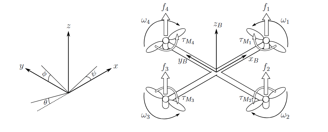
The fundamental principle of quadcopter stability relies on torque cancellation. To maintain a stable orientation, two motors rotate clockwise (CW) while the adjacent pair rotates counter-clockwise (CCW). This arrangement ensures that the net moment about the center of mass is zero; without this pair-wise opposition, the drone would rotate uncontrollably around its vertical axis. Quadcopters typically use either a “plus (+)” or “cross (x)” configuration, with the cross configuration being more common due to its superior stability (Idrissi et al., 2022).
2.2 Control Inputs
The absolute linear position of the quadcopter is defined in the inertial frame axes (). The attitude, i.e. the angular position, is defined in the inertial frame with three Euler angles (), which represent pitch angle, roll angle and yaw angle(figure 3).
Every change in position or attitude is achieved by varying the individual angular velocities () of the four rotors:
-
Thrust (): Simultaneously increasing all rotor speeds causes the vehicle to ascend. The force generated by rotor is , where is the lift constant. Total thrust is defined as .
-
Yaw (): Rotating the drone around the vertical axis is achieved by creating a torque imbalance between the CW and CCW pairs: , where is the drag constant.
-
Roll () and Pitch (): These are achieved by creating a speed differential between opposite rotors. For a distance from the center of mass:
2.3 Mathematical Modeling
The quadcopter is modeled as a rigid body using Newton-Euler equations. The acceleration in the inertial frame is governed by gravity () and the orientation of the thrust vector:
In the body-fixed frame, the angular acceleration is influenced by the external torque (), inertia matrix (), and gyroscopic effects:
3. Pilot Interface and Control Systems
The First-Person View (FPV) experience is defined by the synchronization between the pilot’s inputs and the drone’s visual feedback. An FPV drone can be controlled with a traditional remote controller or with a Motion Controller. A Motion Controller allows they user to maneuver the drone using hand gestures which is easy and convenient. The FPV Goggles is a also used for the FPV Drone. It’s the defining factor for the FPV Drone. It connects to the drone’s camera so that the camera user can have full vision of the drone’s camera (Usama et al., 2021).
3.1 Radio Transmission and Stick Modes
Modern FPV controllers utilize two primary stick configurations. The critical difference between an FPV transmitter and a standard gaming controller is the throttle axis, which lacks a spring-return mechanism to allow for precise altitude maintenance.
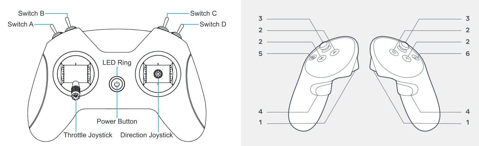
The industry standardizes these controls into two primary layouts:
- Mode 1 (Japanese Hand): Predominantly used in Japan and parts of Europe. The throttle is located on the right gimbal.
- Mode 2 (American Hand): The global standard for FPV. The throttle is located on the left gimbal, which most pilots find more intuitive for separating altitude from directional pitch.
| Mode | Left Stick (Vertical) | Left Stick (Horizontal) | Right Stick (Vertical) | Right Stick (Horizontal) |
|---|---|---|---|---|
| Mode 1 | Pitch | Yaw | Throttle | Roll |
| Mode 2 | Throttle | Yaw | Pitch | Roll |
From a signal processing perspective, the flight controller differentiates between the unipolar throttle and the bipolar command sticks:
- Throttle (): Mapped to a range of .
- Roll, Pitch, and Yaw (): Mapped to a range of .
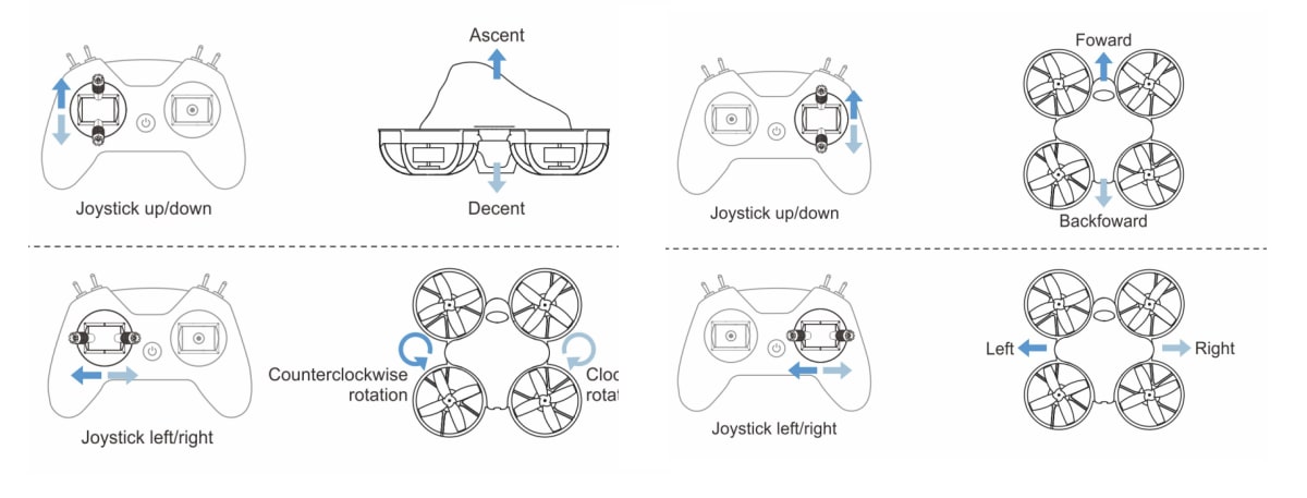
3.2 Flight Modes
FPV drones generally operate across two flight logic modes.
-
Self-Leveling (Angle/Normal Mode): The onboard flight controller uses accelerometers to automatically return the drone to a level horizon when the sticks are centered. This is ideal for beginners but limits maneuverability.
-
Acrobat (Manual Mode): The controller only uses gyroscopes to maintain the current angular rate. If the pilot moves the stick and returns it to center, the drone maintains its current tilted orientation. This allows for flips and rolls but requires constant manual correction.
Although you can use a traditional remote controller to control an FPV quadrotor. There are still a difference on the trottle control in the modern FPV controllers. Take the BetaFPV’s LiteRadio 2 SE Radio Transmitter as an example.
3.3 Visual Feedback (FPV Goggles)
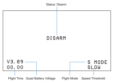
FPV goggles provide the pilot with a low-latency video feed, effectively placing them “inside the cockpit.” Beyond the video feed, an On-Screen Display (OSD) provides critical telemetry data, including battery voltage, signal strength (RSSI), and flight time.
Luukkonen, T. (2011). Modelling and control of quadcopter. Independent research project in applied mathematics, Espoo, 22(22), 1-24. https://sal.aalto.fi/publications/pdf-files/eluu11_public.pdf
Idrissi, M., Salami, M., & Annaz, F. (2022). A Review of Quadrotor Unmanned Aerial Vehicles: Applications, Architectural Design and Control Algorithms. Journal of Intelligent & Robotic Systems, 104(2), 22. https://doi.org/10.1007/s10846-021-01527-7
Ghazbi, S. N., Aghli, Y., Alimohammadi, M., & Akbari, A. A. (2016). Quadrotors Unmanned Aerial Vehicles: A Review. International Journal on Smart Sensing and Intelligent Systems, 9(1), 309–333. https://doi.org/10.21307/ijssis-2017-872
Karahan, M. Development Stages of Quadrotors from Past to Present: A Review. Drones 2025, 9, 840. https://doi.org/10.3390/drones9120840
Usama, A., Dora, M., Elhadidy, M., Khater, H., & Alkelany, O. (2021). First Person View Drone - FPV. The International Undergraduate Research Conference, 5(5), 437–440. https://journals.ekb.eg/article_246400.html
BetaFPV. (2022). LiteRadio 3 radio transmitter user manual. https://support.betafpv.com/hc/en-us/article_attachments/55907267618073