J.Gong
2026-03-29
3.18min
Drone Agent: A PID Implementation for Self-Leveling drones
1. Introduction to PID Control
In 1922, Nicolas Minorsky presented a very clear analysis of the control actions necessary to provide effective control of a system whose exact dynamics were un- known. He analyzed the actions taken by a good helmsman steering a ship and translated these actions into the appropriate mathematical formulations (Bennett, 1993). It is now know as the Proportional-Integral-Derivative (PID) controller. PID is a type of controller that is most commonly used and applied in mechanical systems (Idrissi et al., 2022).
The controller consists of three main components:
-
Proportional (): Acts like a virtual spring that pulls the system toward the desired position; the control action increases as the error gets larger.
-
Integral (): Accumulates the error over time to eliminate steady-state error, ensuring the drone reaches the exact target even in the presence of disturbances like gravity.
-
Derivative (): Acts as a virtual damper to reduce oscillations and prevent the system from overshooting its target.
The idealized control law is expressed as:
2. Mission Controller Architecture
The objective of this chapter is to implement a closed-loop mission controller. This system translates high-level world-frame goals (waypoint coordinates, target altitude, and yaw) into RC-style stick commands (normalized -1 to 1) compatible with the existing Yue drone physics engine.
2.1 Path Generation via Bézier Curves
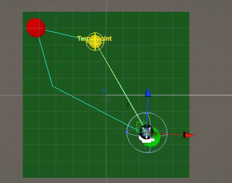
To move between points, the agent generates a path using two Cubic Bézier curves. Given four control points , home to waypoint and back, the position for is defined as:
2.2 Geometric Construction
The path is constructed relative to the “Home” () and “Target” () vectors:
- Forward Vector:
- Orthogonal (Right) Vector: (This handles the lateral expansion of the teardrop).
- Bulge Parameterization: A
widthRatiovariable allows the path to scale from a narrow line to a wide teardrop shape..
2.3 Symmetry and Loop ClosureDescribe the two-phase approach:
The mission follows a two-phase approach to ensure a continuous loop:
- Outbound: Path from Home to Waypoint using a right-hand offset for control points.
- Inbound: Path from Waypoint back to Home using a left-hand offset.
3. Cascaded Control Loops
The system employs a cascaded control scheme where the Outer Loop (Position) provides setpoints for the Inner Loop (Attitude/Velocity).
3.1 The Inner Loop (Attitude & Velocity)
The Inner Loop block features controllers that yield the required rolling and pitching moments τxand τyto regulate horizontal movement. The Inner Loop block requires the current quadcopter attitude as well as reference signals for roll and pitch to obtain its output(Paredes et al., 2021)
3.2 The Outer Loop (Position & Navigation)
the Outer Loop block, which features controllers that yield the required thrust differential and yawing moments as well as the desired reference signals.
4. Implementation Logic
4.1. Vertical Direction
During takeoff, the controller focuses exclusively on vertical error (). The vertical force is mapped to a normalized throttle value ():
4.2. Path Following (6-DOF Control)
Following a path requires a look-ahead method. Given current position and look-ahead target on the path, the position error is defined as:
The Outer Loop converts this error into a Desired Velocity in the world axis:
To translate these into drone-relative commands (Pitch/Roll), the world velocity is projected onto the drone’s Heading Axis:
- Forward Basis:
- Right Basis:
- Projections:
The Inner Loop then calculates the error between desired and actual velocity to produce stick inputs:
- Pitch (Right Vertical): Based on longitudinal velocity error ().
- Roll (Right Horizontal): Based on lateral velocity error ().
The drone should yaw toward its movement direction once a “velocity threshold” (0.5 m/s) is met.
- Target Yaw:
- Yaw Error:
- Output:
5. Pilot Assistance UI
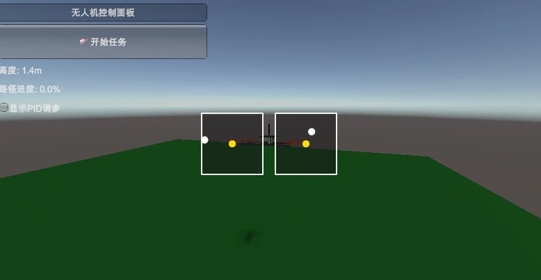
By calculating these normalized joystick rates, the system can visualize the “AI’s intent” on the HUD. This serves as a co-training hinter, showing human pilots the optimal stick positions for maintaining the designated path.
Bennett, S. (1993). Development of the PID controller. IEEE Control Systems, 13(6), 58–62. https://doi.org/10.1109/37.248006
Idrissi, M., Salami, M., & Annaz, F. (2022). A Review of Quadrotor Unmanned Aerial Vehicles: Applications, Architectural Design and Control Algorithms. Journal of Intelligent & Robotic Systems, 104(2), 22. https://doi.org/10.1007/s10846-021-01527-7
Lynch, K. M., & Park, F. C. (2017). Modern Robotics: Mechanics, Planning, and Control (1st ed.). Cambridge University Press. https://doi.org/10.1017/9781316661239
Paredes, Juan, Prashin Sharma, Brian Ha, et al. “Development, Implementation, and Experimental Outdoor Evaluation of Quadcopter Controllers for Computationally Limited Embedded Systems.” arXiv:2105.14231. Preprint, arXiv, June 1, 2021. https://doi.org/10.48550/arXiv.2105.14231.